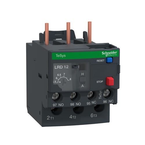
Information about Thermal Relay 5.5-8A
The Schneider Electric TeSys LRD12 thermal overload relay is a differential overload relay designed for electric motor protection. It features a thermal adjustment range of 5.5 to 8 A, trip class 10A, and phase-loss sensitivity, allowing the motor to be protected against prolonged overloads and unbalanced operation. It is specifically designed for direct association with compatible Schneider Electric TeSys D / TeSys Deca contactors.
The LRD12 includes 1 normally open auxiliary contact and 1 normally closed auxiliary contact for signaling and control circuit operation. It can be installed directly under the contactor or independently on a rail or plate using the corresponding specific accessories.
Main features of the Schneider Electric LRD12
- Brand: Schneider Electric.
- Range: TeSys.
- Family: TeSys LRD / TeSys Deca Protect.
- Reference: LRD12.
- Type: differential thermal overload relay.
- Application: motor protection.
- Thermal setting range: 5.5-8 A.
- Trip class: 10A according to IEC 60947-4-1.
- Phase-loss sensitivity: yes.
- Auxiliary contacts: 1 NO + 1 NC.
- Rated operational voltage: up to 690 V AC.
- Frequency: 0-400 Hz.
- Insulation voltage Ui: 690 V according to IEC 60947-4-1.
- Impulse withstand voltage Uimp: 6 kV.
- Mounting: direct under contactor or on rail/plate using accessories.
- Terminals: screw terminals.
- Degree of protection: IP20.
- Width: 45 mm.
- Depth: 70 mm.
- Weight: approximately 0.124 kg.
Adjustable thermal protection between 5.5 and 8 A
The front of the LRD12 features a selector that allows the thermal protection to be adjusted within a range of 5.5 to 8 A. The setting must be adapted to the rated current indicated on the motor nameplate and to the actual operating conditions of the installation.
The relay monitors the current flowing to the motor and trips when it detects a sustained overload condition that could cause harmful heating of the windings.
Trip class 10A
The Schneider Electric LRD12 belongs to trip class 10A according to IEC 60947-4-1. This class defines the relay’s time response to certain overcurrents and is especially suited to motors with normal starting conditions.
The selected trip class must be compatible with the starting time and the characteristics of the driven machine.
Differential relay sensitive to phase loss
In addition to overload protection, the LRD12 incorporates sensitivity to phase loss or phase imbalance. Schneider Electric specifies tripping at a current of 130% of Ir in two phases when the current in the third phase is zero.
This function is especially important in three-phase motors, since loss of one phase can cause overcurrents in the remaining phases, loss of torque, and a rapid increase in motor temperature.
Thermal trip threshold
The manufacturer specifies a trip threshold of 1.14 ± 0.06 times Ir according to IEC 60947-4-1. The Ir value corresponds to the current selected using the relay’s front adjustment.
In this way, the device’s thermal behavior can be adapted to motors with rated currents within its 5.5 to 8 A range.
Compatible with TeSys D and TeSys Deca contactors
The LRD12 is designed for direct mounting with various Schneider Electric TeSys contactors, including:
- LC1D09.
- LC1D12.
- LC1D18.
- LC1D25.
- LC1D32.
- LC1D38.
Direct connection of the relay under the contactor creates a compact motor control and protection assembly, reducing internal wiring and the space required inside the panel.
Independent mounting using accessories
In addition to direct mounting under the contactor, the thermal relay can be installed separately using specific accessories.
Schneider Electric provides for mounting:
- Directly under a compatible contactor.
- On a rail using a specific accessory.
- On a plate using a specific accessory.
For certain independent mounting applications, the Schneider Electric LAD7B106 adapter can be used, always checking the compatibility of the configuration beforehand.
1 NO + 1 NC auxiliary contacts
The LRD12 includes one normally open contact and one normally closed contact integrated for signaling and control circuits.
These contacts allow the relay trip to be used to:
- Interrupt the contactor coil supply.
- Signal an overload.
- Send fault information to an automation system.
- Trigger an alarm.
- Integrate the relay into interlocking and protection circuits.
The conventional thermal current of the signaling circuit is 5 A.
Manual or automatic reset
The TeSys LRD family allows selection of manual or automatic reset operation. The front of the device includes a blue pushbutton for the reset function and a red stop pushbutton.
The reset mode should be selected according to the level of safety required by the machine. In applications where an automatic restart could create a hazardous situation, the appropriate configuration must be used and the safety measures defined in the system design must be respected.
Ambient temperature compensation
The LRD12 incorporates thermal compensation to maintain stable performance despite changes in ambient temperature. Schneider Electric specifies compensation between -20 and +60 °C.
This feature helps keep the protection threshold related to the motor’s actual current within the expected ambient range.
Operating voltage up to 690 V AC
The power circuit supports a rated operational voltage of up to 690 V AC and frequencies from 0 to 400 Hz.
The rated insulation voltage is 690 V according to IEC 60947-4-1, while the impulse withstand voltage Uimp reaches 6 kV.
Screw terminals
The Schneider Electric LRD12 uses screw terminals for both the power circuit and the auxiliary circuit.
For the power circuit, depending on conductor type, it accepts:
- Flexible without terminal: 1.5 to 10 mm².
- Flexible with terminal: 1 to 4 mm².
- Rigid: 1 to 6 mm².
For the control and signaling circuit, it accepts up to two conductors of 1 to 2.5 mm², depending on the configuration.
The tightening torque specified by Schneider Electric is 1.7 Nm for both the power circuit and the control terminals.
Compact format
The relay has a reduced size that makes it easy to combine with TeSys contactors inside automation panels:
- Width: 45 mm.
- Depth: 70 mm.
- Weight: approximately 0.124 kg.
Its width matches that of many compatible TeSys D contactors, creating a compact assembly when mounted directly under the contactor.
IP20 protection rating
The LRD12 has an IP20 degree of protection according to IEC 60529. It must be installed inside a panel or enclosure that provides the degree of protection required by the environment and application.
Environmental conditions
- Operating temperature: -20 to +60 °C without derating.
- Storage temperature: -60 to +70 °C.
- Protection treatment: TH according to IEC 60068.
- Vibration resistance: 6 Gn according to IEC 60068-2-6.
- Shock resistance: 15 Gn for 11 ms.
- Flammability rating: V1 according to UL 94.
The thermal relay does not replace short-circuit protection
The LRD12 is primarily designed to protect the motor against overloads and phase loss. It does not replace a dedicated short-circuit protection device.
The starter must be completed with a circuit breaker, motor circuit breaker, or fuses properly coordinated with the contactor and thermal relay in accordance with Schneider Electric coordination tables.
Applications of the Schneider Electric LRD12
The thermal relay can be used in numerous motor drive systems whose rated current falls within the 5.5 to 8 A range:
- Water pumps.
- Fans and extractors.
- Compressors.
- HVAC systems.
- Conveyor belts.
- Industrial machinery.
- Pumping equipment.
- Automation panels.
- Direct-on-line motor starters.
- Control systems with TeSys D contactors.
Standards and certifications
The Schneider Electric LRD12 is developed in accordance with the main international standards applicable to protection relays and switching equipment:
- IEC 60947-4-1.
- IEC 60947-5-1.
- EN 60947-4-1.
- EN 60947-5-1.
- UL 508.
- CSA C22.2 No. 14.
The official documentation also lists certifications such as UL, CSA, CCC, DNV, BV, RINA, and Lloyd's Register, among others.
Technical data of the Schneider Electric LRD12
- Manufacturer: Schneider Electric.
- Reference: LRD12.
- Range: TeSys.
- Product: TeSys LRD / TeSys Deca Protect.
- Type: differential thermal overload relay.
- Application: motor protection.
- Setting range: 5.5-8 A.
- Trip class: 10A.
- Trip threshold: 1.14 ± 0.06 x Ir.
- Phase-loss sensitivity: yes.
- Phase-loss trip: 130% of Ir in two phases with the third at 0.
- Auxiliary contacts: 1 NO + 1 NC.
- Ith of signaling circuit: 5 A.
- Rated operational voltage: 690 V AC.
- Frequency: 0-400 Hz.
- Ui: 690 V according to IEC 60947-4-1.
- Uimp: 6 kV.
- Reset: manual or automatic.
- Front control: red stop pushbutton and blue reset pushbutton.
- Temperature compensation: -20 to +60 °C.
- Mounting: direct under contactor or independent with accessories.
- Compatible contactors: LC1D09, LC1D12, LC1D18, LC1D25, LC1D32 and LC1D38.
- Terminals: screw.
- Tightening torque: 1.7 Nm.
- Width: 45 mm.
- Depth: 70 mm.
- Weight: 0.124 kg.
- Degree of protection: IP20.
- Operating temperature: -20 to +60 °C.
- Storage temperature: -60 to +70 °C.
TeSys thermal protection for 5.5 to 8 A motors
The Schneider Electric LRD12 provides adjustable protection between 5.5 and 8 A for electric motors, combining class 10A thermal tripping with phase-loss sensitivity. Its 1 NO + 1 NC auxiliary contacts make it easy to integrate tripping into the starter’s control and signaling circuit.
The ability to install it directly under compatible TeSys D contactors makes it possible to build compact starter assemblies, while the independent mounting accessories expand installation options. The setting must be adjusted according to the motor’s rated current, and short-circuit protection must be completed with a properly coordinated device.
